
| Robotic Art Studio: | Spring 1999 |
| Group: | Superficial Surfaces |
| Eric Wilcox Margaret McCormack Ariel Mayrose Gabriel Z Colwell-Lafleur |
|
| Date: | April 29, 1999 |
| Related Documents: | MM74HCT164.pdf DS2003.pdf |
Using this 8-bit shift register is a convenient way to map a serial stream of signals to parallel output. But what exactly does this mean, and when is it useful? We will try to answer these questions below, as well as give you an example application of where the shift register came in handy.
The shift register requires a minimum of three stamp pins to operate. One pin is used as input, one for a clock signal, and one for a clear signal. All operations happen on the leading edge of the clock signal. Values are passed down the line of outputs with each cycle of the clock... This will hopefully become clearer with the following diagrams.
Both the input and clear signals can be wired directly to stamp pins. Setting the the clear pin to low will cause all the outputs of the shift register to be low. Setting the clear pin to high enables you to change the values on the output puts using the clock signal and input as described later on.
The Basic Stamp is capable of generating a clock signal by using the PWM (Pulse-Width-Modulation) command. For example:
PWM 7, 255, 8
will pulse out a clock signal between 0V and +5V for 8 cycles on PIN7. The wave produced can be visualized as:
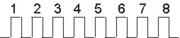
With each pulse, the input signal (which can be a connection to a Pin on the basic stamp, set to high or low) shifts the previous signals down the register and sets Qa. If, for example, you want the output (Qa-Qh) of the shift register to equal 11000001, the code might look something like the following:
'set the last three pins as output

PINS = %11100000
'give the pins meaningful symbols

SYMBOL input = PIN5

SYMBOL clear = PIN6

SYMBOL clock = PIN7
'set the clear to high

HIGH clear
'set input to high for last 1

HIGH input
'pulse out one clock signal

PWM clock, 255, 1
'pulse out the 5 zeros

LOW input

PWM clock, 255,5
'pulse out two more ones

HIGH input

PWM clock, 255,2
The shift register has D-Type flip-flops on the outputs. This means that once you set the output high/low, it will maintain that value. The only way to change it is to set clear to low (which clears all outputs) or shift a new set of values down the outputs.
Here is a link to the technical documentation for the MM74HCT164 shift register: MM74HCT164.pdf
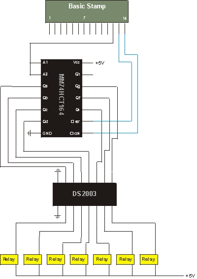
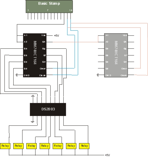
In the Superficial Surface project, we had a lot of inputs and outputs. Since we were limited by the number of pins on a basic stamp, we used the 8-bit Shift register to "demux" a signal to multiple outputs. By using the register, we were able to control 7 outputs with only 3 stamps pins. With an additional shift-register, we could have easily controlled 14 outputs off the same 3 pins!
Circuit with 1 Shift Register
Circuit with 2 Shift Registers
Our problem was that we wanted to control 12 valves from a single stamp. Since the stamp only has at most, 8 output pins, we had to come up with a better solution. The shift register allowed us to multiplex a signal to a set of relays which triggered our valves. We could turn on and off each valve by setting the input, shifting the bit down the register, and stopping when the correct sequence was in place.
To add an additional 7 outputs, all that is needed is another MM74HCT164. Wire the Qh pin of the first register to the inputs (A1, A2) of the second register, connect the clock pins on both registers to the same stamp pin, connect the clear pins on both registers to the same stamp pin. The values move down the first register and the clock signal oscillates. When a value reaches Qh on the first register, it is transferred to the the second register and continues on.
When we first hooked up the shift-register, we were only attached to one of the input pins (A1). This caused a lot of strange behavior since the register requires both inputs to operate correctly. For our purposes, it was easiest to just connect both inputs together. It is also possible to hook in separate sources to the two inputs in which case the signals are logically "AND"ed together to produce the value which will be shifted down the outputs.
You have to make sure that all the pins are set to output as in the sample code above. We forgot to set them as such when we first hooked up the shift-register and were confused as to why nothing was working.
Tip: you don't always have to shift in multiples of 8. We were only interested in firing one relay at a time so in our code we set the clear bit to low to clear all the pins, set the clear back to high, set input to high, and then PWM only as many times as we needed to fire the appropriate relay. The pulses happen so fast that only the relay we were interest in actually got fired. Intermediate firing of the relays did not occur as the clock signal propagated values down the outputs.